ats-logo
Key Projects
SCOPE:

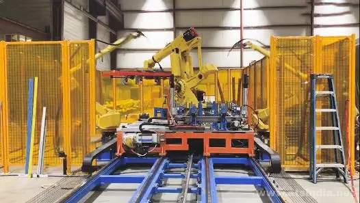
To design and build an Automated Robotic Weld Cell for door frames. The system includes the assembly of side jams and head jams with the tack weld process, full weld process, automated weld inspection, grinding process, transfer shuttle, robot EOAT, and outgoing roller conveyor.

EXISTING PROCESS:

A standalone weld fixture with manual loading/unloading, resulting in increased cycle time.

CHALLENGES:

Achieving critical cycle time for the weld process, accommodating multiple product variants into a common weld station, and building a custom grinding station to grind additional weld beads at a 45° angle.

OUR SOLUTION:

ATS designed and built the complete automated robotic weld cell. The complete weld fixture was designed to accommodate all required variants and is mounted to a shuttle for transfer in and out of the robotic weld cell. Our solution achieved the required cycle time along with the quality expectations of the customer.

SCOPE:

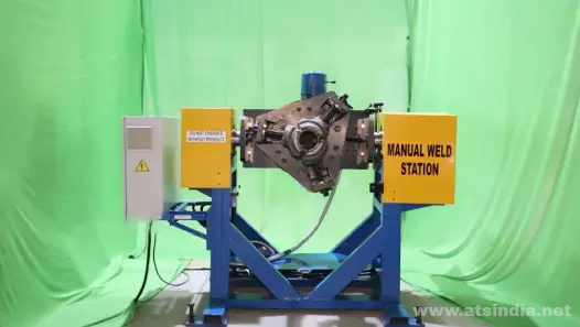
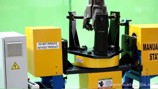
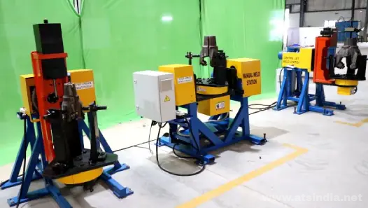
To build various semi-automatic weld stations for performing welding on rotary drill bits. These bits are used in the mining industry and are heavy, making them difficult to handle.

EXISTING PROCESS:

The current process involves manually handling the products to achieve the required weld position. Once the product is positioned correctly, the operator proceeds with the welding operation.

CHALLENGES:

The heavy weight of the product makes it difficult to handle manually. The proposed station must accommodate all product variants, ranging from 137mm to 580mm in height. Additionally, the weld stations must provide ergonomic access to all weld locations.

OUR SOLUTION:

ATS designed and built semi-automatic weld stations for M-joint, manual weld, and center-jet welding processes on tri-cone drilling bits. The systems are designed to accommodate all product variants and achieve the required weld positions ergonomically.

SCOPE:

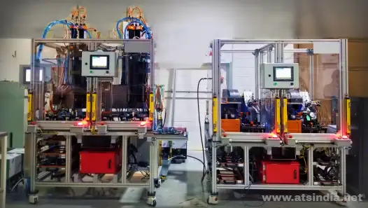
To automate the assembly of the motor and latch, test the assembled latch under half and full lock conditions, and verify motor connectivity. Automatically laser-etch the part if it passes, and reject it if it fails the test conditions.

EXISTING PROCESS:

Assembly was done manually using nut runners, and the locking conditions were tested manually.

CHALLENGES:

Accommodating the number of variants in fixtures and to poka-yoke to ensure the correct part goes into the correct fixture. Automating the testing of the assembly at half and full lock conditions.

OUR SOLUTION:

The process was divided into two stations. In the first station, assembly was automated. In the second station, testing was done. The latch assembly was checked at both half and full lock conditions using a servo pneumatic cylinder.

SCOPE:

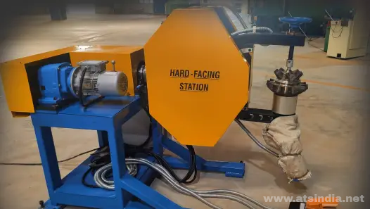
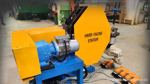
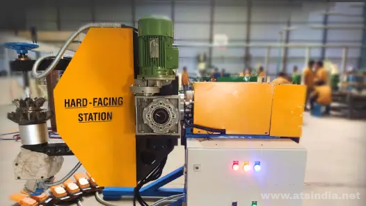
To design and build a Hard Facing Station for the cones of Tri-Cone Drilling Bits, which are used in the mining industry. These drill bits come in various product variants and are often heavy. Hard facing is a carbide material deposition process using extreme heat over the surface of the drill bit cone. Three of these cones join to form a Drill Bit Each. Three of these cones are joined to form a single drill bit.

EXISTING PROCESS:

Currently, the hard facing process involves manual loading and unloading. The cones are manually placed and clamped onto the fixture, then rotated at multiple angles to reach the desired positions for hard facing.

CHALLENGES:

Due to the product’s heavy weight, manual handling is difficult. The proposed station needs to accommodate all product variants, and all hard facing locations must be ergonomically accessible.

OUR SOLUTION:

ATS designed and built a fully automated robotic weld cell. The complete weld fixture was designed to accommodate all required variants and was mounted on a shuttle for easy transfer in and out of the robotic weld cell. Our solution met the required cycle time and achieved the quality expectations of the customer.
SCOPE:

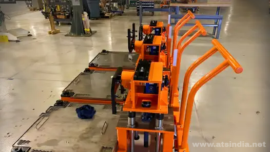
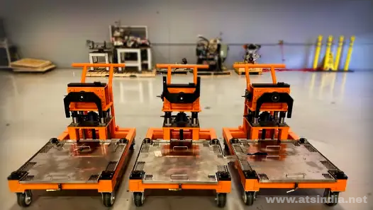
To design and build a cart for handling engine assemblies. The cart needs to facilitate the sub-assembly of the engine and testing, while being capable of changing the engine’s orientation as needed.

EXISTING PROCESS:

Currently, the engine was assembled at a stationary station and then carried to assembly areas using an overhead crane or forklift.

CHALLENGES:

The engine weighs around 210 kg, so the cart needed to be designed to provide access to the engine for assembly at all locations.

OUR SOLUTION:

We designed and built a cart manipulator capable of carrying the complete engine assembly and performing sub-assemblies conveniently.

Our expert teams will reach out to you in no time
Request a Free Quote